.
.
.
Schede e sottoassiemi custom
Schede driver
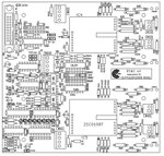
Il pilotaggio dei semiconduttori utilizzati nei moduli di potenza è affidato ad un range di apposite schede driver.
Tutte le schede di pilotaggio degli IGBT sono dotate di diagnostica locale che, in caso di funzionamento anomalo, bloccano i semiconduttori ed inviano un segnale di allarme alla scheda di controllo DSP.
Appositi LEDs segnalano localmente la tipologia dell'allarme, il reset degli allarmi può venire effettuato direttamente dalla scheda DSP o disalimentando e rialimentando nuovamente la scheda driver.
I driver si connettono tramite flat-cable alla scheda DSP; tramite i flat cable la schda DSP provvede a fornire le adatte tensioni di alimentazione ai driver.
Alcune delle schede driver prevedono già a bordo i sensori isolati di tensione (i relativi segnali vengono portati alla schda DSP tramite flat-cable.
Anche il pilotaggio dei tiristori viene effettuato tramite apposite schede che si interfacciano direttamente alla scheda DSP.
Dato che per fornire gli impulsi di gate ai tiristori occorre un'alimentazione più potente, cosicchè la schda DSP non è in grado di fornire l'alimentazione necessaria.
Le schede driver per i tiristori si incaricano di realizzare localmente gli impulsi di accensione e i relativi sfasamenti cosicchè viene impiegato solamente 1 canale della scheda DSP per comandare tutti e 6 i componenti.
In questo caso si utilizza una tensione di 24Vcc che è totalmente isolata sia dalla scheda DSP che dai gates dei tiristori.
Schede driver per IGBT
CODE
DOCUMENTATION
DESCRIPTION
1x IGBT LEG and diagnostics
This board is suitable to drive up to 400A-1200V IGBT inverter leg and interfaces with the DSP control boards through one 20 wire ribbon cable and the 4 twisted wires of Hall sensor. The electronic board is comprehensive of diagnostic of:
- IGBT1 desaturation
- IGBT2 desaturation
- Overcurrent
- Cross-conduction
- Connector out
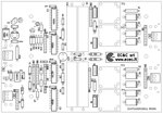
2x Paralled IGBT LEG and diagnostics
This board is suitable to drive up to 2x 400A-1200V IGBT inverter leg connected in parallel and interfaces with the DSP control boards through only one 20 wire ribbon cable and the 4 twisted wires of 2x Hall sensor. The electronic board is comprehensive of diagnostic of:
- IGBT1 desaturation
- IGBT2 desaturation
- Overcurrent
- Current Unbalancing
- Cross-conduction
- Partially removed connector
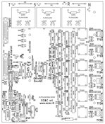
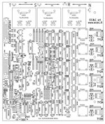
3Ph inverter driver
This board is suitable to drive a 3Ph inverter made by 3x 400A-1200V IGBT Legs and interfaces with the DSP control boards through only one 20 wire ribbon cable (Drive and allarm) and one 40 wire ribbon cable (signals). The electronic board is made by three section (each related at one output fase); each section is comprehensive of diagnostic of:
- IGBT1 desaturation (Ph1, Ph2, Ph3)
- IGBT2 desaturation (Ph1, Ph2, Ph3)
- Overcurrent (Ph1, Ph2, Ph3)
- Current Unbalancing (Ph1, Ph2, Ph3)
- Cross-conduction (Ph1, Ph2, Ph3)
- Partially removed connector
The driver board is equipped by:
- AC-DC insulated voltage sensor: Ph1 Vout , Ph2 Vout , Ph3 Vou,t Vdc Bus 1, Vdc Bus 2
- AC-DC Current sensor: Ph1, Ph2, Ph3
- Thermal sensor of heatsink: Ph1, Ph2, Ph3
- Thermostat of the magnetic components: Ph1, Ph2, Ph3
Schede driver per tiristori
CODE
DOCUMENTATION
DESCRIPTION
6TY Static Switch
This board fires up to 6 tyristor toghether. In function of the position of a jumper, the board acts as Normally Open switch or as a Normally Closed switch. This driver board interfaces with the DSP controller board by two 20-wire-ribbon-cable; the first is used for the drive and allarm signals, the second for the temperature, current and voltage signals.
The driver board must by supplied by an external 24Vdc voltage; the input signals are optically insulated; obviously also the gate firing circuits are fully insulated.
The statich switch is activated by a square wave (about f=10kHz duty-cycle=50%). Both the states Zero and +15V deactive the board. In this way, if we connects two driver board (the first setted as NO, the second as NC), we realize a static switchgear drived by only one control signal.
Using thi board with a tyristor bridge we make a ON-OFF controlled rectifier.
6TY full controlled bridge
This board drives a full controlled 6 tyristor bridge and interfaces with the DSP controller board by two 20-wire-ribbon-cable; the first is used for the drive and allarm signals, the second for the temperature, current and voltage signals.
The driver board must by supplied by an external 24Vdc voltage; the input signals are optically insulated; obviously also the gate firing circuits are fully insulated.
The firing angle is in proportion to the duty-cycle of the input signal; so a duty-cycle about equal 1 stops the bridge, a duty-cycle about zero make the full-conduction of the bridge, a duty cycle about 50% make a partial conduction of the bridge.
A separated "enable" input signal is provided.
2x Capsule Type Tyristors
This board is able to drive two capsule tipe tyristor following the prescriptions of the ABB Application Note “Gate-drive recommendations for PCT_ 5SYA 2034_02”; so is suitable to fire the big, amplified gate, tyristors.
Both the tyristors are fired in the same time by a first strong pulse, followed by a string of smaller pulses.
When the input signal is in logic state 1 the tyristors are fired.
According to the position of a jumper, the logic signal 1 can be 12-15V or 24V.
The driver board must by supplied by an external 24Vdc voltage; for the maximum noise immunity, the input signal is optically insulated; obviously also the gate firing circuits are fully insulated.


